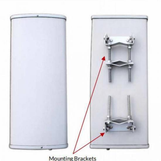
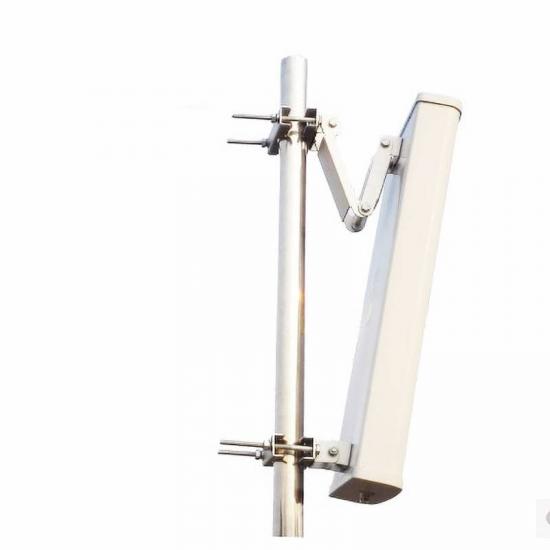
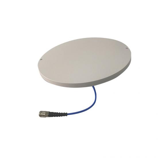
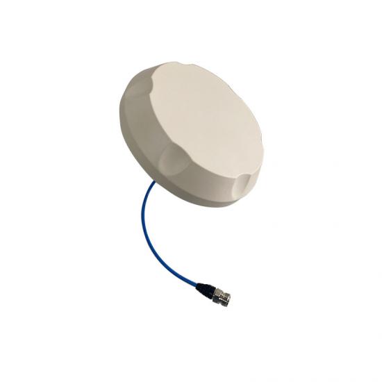
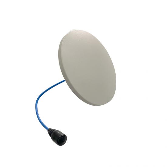
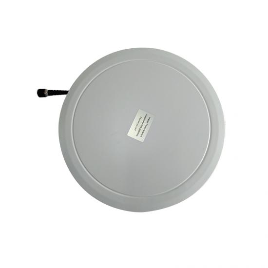
Product Name
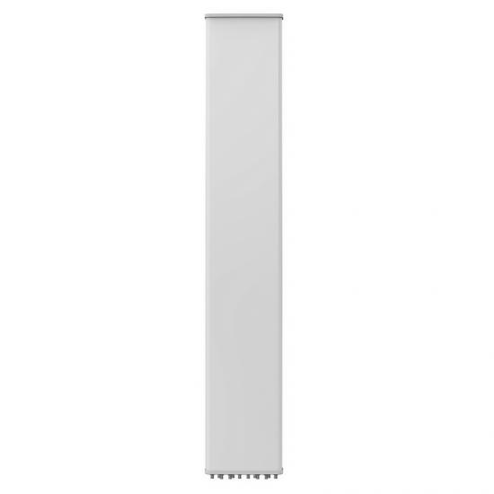
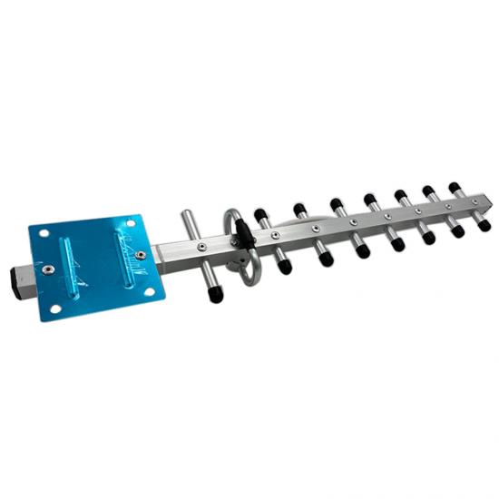
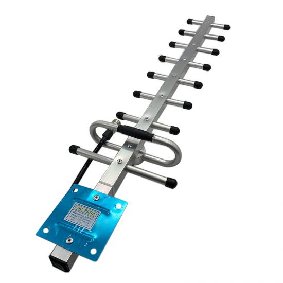
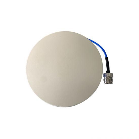
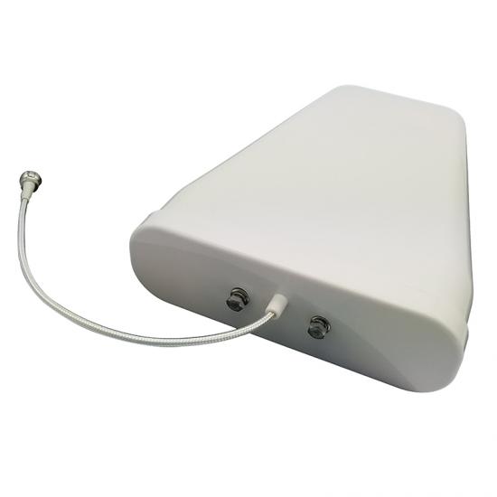
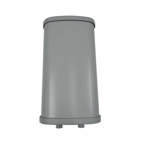
8 Ports 698~960MHz/1710~2690MHz 65°/65° 16.1/18.5dBi Base Station Antenna
Product Features
◆ Low Passive Inter-modulation
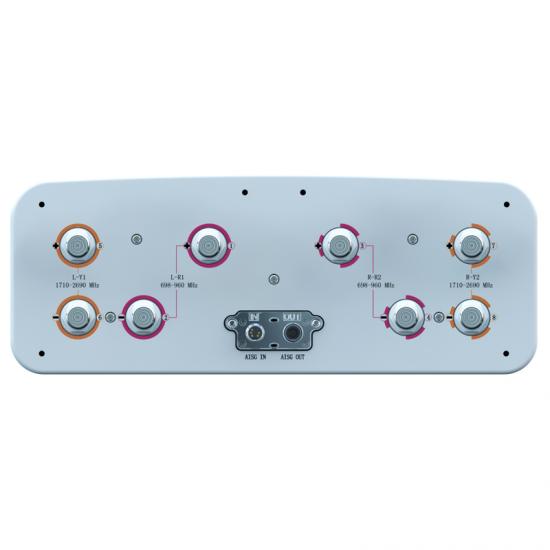
◆ Uses the new 4.3-10 connector, which is 40% smaller than traditional 7/16 DIN connector
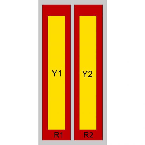
◆ Includes 1 cross polarization array(2ports) for low band(698-960MHz) and 2 cross polarization arrays for high band(1710-2690MHz)
Technical Specifications
|
Frequency Range(MHz) |
R1/R2: 698-960 |
|||
|
|
698-806 |
790-862 |
824-894 |
880-960 |
|
Polarization |
±45° |
|||
|
Gain at mid tilt (dBi) |
15.0 |
15.5 |
15.8 |
16.1 |
|
Gain over all tilts (dBi) |
14.8±0.6 |
15.3±0.6 |
15.6±0.3 |
15.9±0.6 |
|
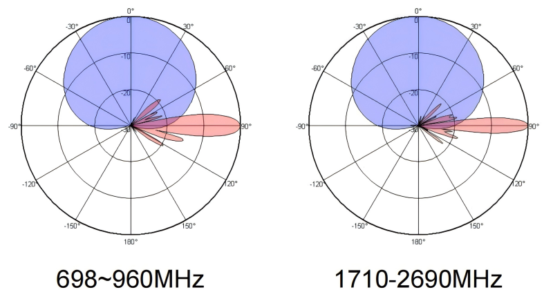
Horizontal 3dB beamwidth (°) |
68±5 |
65±4 |
64±4 |
63±5 |
|
Vertical 3dB beamwidth (°) |
11.3±0.8 |
10.4±0.6 |
9.9±0.7 |
9.2±0.7 |
|
Front-to-back ratio (dB) Total power, ±30° |
>23 |
>24 |
>26 |
>26 |
|
Cross-polar ratio (dB) (at Boresight) |
>18 |
>20 |
>21 |
>20 |
|
Electrical downtilt (°) |
2~12 |
|||
|
Sidelobe suppression (dB) (First sidelobe above main beam) |
>16 |
>16 |
>16 |
>16 |
|
VSWR |
<1.5 |
|||
|
Isolation: intra-system (dB) |
≥25 |
|||
|
Isolation: inter-system (dB) |
R1//R2 ≥ 25 R1, R2//(Y1, Y2) ≥ 28 |
|||
|
Intermodulation IM3 (2×43dBm carrier) |
≤-153dBc |
|||
|
Impedance (Ω) |
50 |
|||
|
Max. Power per Input(W)@50℃ |
500 |
|||
|
Frequency Range(MHz) |
Y1/Y2: 1710-2690 |
|||
|
|
1710-1920 |
1920-2200 |
2200-2490 |
2490-2690 |
|
Polarization |
±45° |
|||
|
Gain at mid tilt (dBi) |
17.5 |
18.0 |
18.1 |
18.5 |
|
Gain over all tilts (dBi) |
17.4±0.5 |
17.8±0.5 |
17.9±0.6 |
18.4±0.5 |
|
Horizontal 3dB beamwidth (°) |
68±5 |
65±5 |
64±6 |
60±6 |
|
Vertical 3dB beamwidth (°) |
6.9±0.6 |
6.1±0.6 |
5.5±0.5 |
5.5±0.5 |
|
Front-to-back ratio (dB) Total power, ±30° |
>26 |
>26 |
>27 |
>26 |
|
Cross-polar ratio (dB) (at Boresight) |
>18 |
>20 |
>19 |
>18 |
|
Electrical downtilt (°) |
2~12 |
|||
|
Sidelobe suppression (dB) (First sidelobe above main beam) |
>17 |
>17 |
>17 |
>16 |
|
VSWR |
<1.5 |
|||
|
Isolation: intra-system (dB) |
≥25 |
|||
|
Isolation: inter-system (dB) |
≥ 28 |
|||
|
Intermodulation IM3 (2×43dBm carrier) |
≤-153dBc |
|||
|
Impedance (Ω) |
50 |
|||
|
Max. Power per Input(W)@50℃ |
250 |
|||
|
Lightning Protection |
DC Ground |
|||
Mechanical Specifications
Connector
8×4.3-10-Female
Connector Position
Bottom
Height×width×depth (mm)
1999×446×165
Packing Size (mm)
2290×510×215
Antenna weight (kg)
30.5
Installation Kit Weight (kg)
5.5
Packing Weight (kg)
43.2
Wind load (N, at 150km/h) Frontal/Lateral/Rear
705/190/650
Max. Wind Velocity (km/h)
250
Radome Material
Fiberglass
Radome Color
Gray
Mechanical tilt (°)
0~10
Operating Temperature (°C)
-50~65
Mounting Hardware (mm)
Ф50~Ф115
Integrated RET Properties
|
RET model |
MRCU-MQ10P2 |
|
RET type |
Integrated (Replaceable) |
|
RET protocol |
AISG 2.0 SRET |
|
Power supply(V) |
10-30 DC |
|
Power consumption(W) |
≤0.6 (Idle,12V),≤6 (In motion,12V) |
|
Adjustment time (Full Range) |
<4Mins |
|
Adjustment cycles |
>50,000 |
|
Temperature range (℃) |
-40~65 |
|
Lightning protection |
3KA(8/20μs) @ Pin5 & Pin3; 5KA(8/20μs) @ Pin1 / Pin6 & Pin7 |
|
Connectors |
2×8 Pin circle connector according to IEC 60130-9 and AISG. Daisy chain in:Male,Daisy chain out:Female Pin1:12V;Pin3:RS485B;Pin5:RS485A;Pin6:10-30V; Pin7:GND;Pin2&Pin4&Pin8:N/C |
Application
